So here it is...if you don't know what 'it' is, you need to read the last 3 or 4 posts. If you don't, you won't appreciate the magnitude of this task and the sheer skill, genius and dedication it has required to do it...yeah right!! Seriously though.......I bet you couldn't bloody do it!
Anyway, after all the holes of the re-inforcing plate were plug welded, the welds were ground smooth...
Then it was Etch Primed.. Ultimately, I'll remove this primer and properly 2PK Epoxy Prime it. Later, I'll apply Cavity Wax under the plate for extra rust protection...
Before I go....check out the fit of this baby!!...not impressed?....ahh
Right, now what's next..?!
Thursday, 10 January 2013
Plug Welding the Chassis Re-Inforcement
Now the Re-Inforcement Plate is fabricated, it's time to prep it for welding. It will be Plug Welded into place so I drilled 7mm holes at roughly 30mm spacing. Unfortunately I drilled 5 or 6 holes in the wrong place so I needed to weld-up those holes and re-drill them in the right spots.
Here are the holes drilled.
When I had to fill the 'mistake' holes I put a copper pipe behind the hole to give me something to weld against.
Once the holes were drilled in the right place(!), the surfaces to be welded together were painted with weld through primer. Actually, I really wanted to do this right because it's an important structural piece - and I needed to get good weld penetration for strength. So I marked through the holes down onto the surface of the floor and carefully removed the primer at these points using a paper towel and thinners. This meant I would be Plug Welding straight onto the bare metal and would likely give me a stronger weld.....yes, very anal!
Then the plate was welded into place - but it wasn't bloody easy! All the welding on it had taken its toll so it was pretty warped. This meant it took some serious hammering to shape it into place as I plug welded it in strategically and very carefully!
Here it is all nicely welded into place - looks easy doesn't it...well you can just 'shut it' right?!!
Next post shows it ground nice and smoooooth....
Here are the holes drilled.
When I had to fill the 'mistake' holes I put a copper pipe behind the hole to give me something to weld against.
Once the holes were drilled in the right place(!), the surfaces to be welded together were painted with weld through primer. Actually, I really wanted to do this right because it's an important structural piece - and I needed to get good weld penetration for strength. So I marked through the holes down onto the surface of the floor and carefully removed the primer at these points using a paper towel and thinners. This meant I would be Plug Welding straight onto the bare metal and would likely give me a stronger weld.....yes, very anal!
Then the plate was welded into place - but it wasn't bloody easy! All the welding on it had taken its toll so it was pretty warped. This meant it took some serious hammering to shape it into place as I plug welded it in strategically and very carefully!
Here it is all nicely welded into place - looks easy doesn't it...well you can just 'shut it' right?!!
Next post shows it ground nice and smoooooth....
Joining the Chassis Re-inforcement Plate Sections
Got a new Disc Sander delivered under guarantee after the old one packed up; so I cut and sanded the four Chassis Re-inforcement Plate Sections so they fit over the Trunk Floor as 'perfectly' as I could.
In order to join them easily I used scraps to create a kind of bridge - bending them at the end gave me something to clip the Welder 'return-clamp' to.
Once the pieces were tack welded together, I could remove the bridge pieces and weld the 4 sections together permanently... Doing it bit by bit, and moving around the part minimised distortion from heat build-up.
Here's the completed weld..
....and here's the entire panel with the welds ground smooth on the top and bottom.
In order to join them easily I used scraps to create a kind of bridge - bending them at the end gave me something to clip the Welder 'return-clamp' to.
Once the pieces were tack welded together, I could remove the bridge pieces and weld the 4 sections together permanently... Doing it bit by bit, and moving around the part minimised distortion from heat build-up.
Here's the completed weld..
....and here's the entire panel with the welds ground smooth on the top and bottom.
Friday, 7 December 2012
Joggle Bends, Sheet Metal Brakes and other headaches..
No I haven't been sitting in the warmth of the Living Room with my feet up watching 'Homeland' for the past couple of weeks...well, at least, not all the time! I've been struggling with 'Joggle Bends' - no that's not a euphemism.. Actually the garage is away from the house without any heating. It's about freezing outside so I'm wearing two wool jumpers with thermals under my overalls - mobility is a bit of an issue under multiple layers!
Anyway, when I cut the Trunk Floor out all those months back I had to trash a strip of metal that essentially stiffened the transmission/gearbox mounts. This innocent looking piece of metal mated perfectly to the trunk floor beneath it with Joggle Bends along either edge - a Joggle Bend is basically a step in the metal.
Here's the strip before I replaced the floor back in January this year..
I thought fabricating a new strip would be easy but I realise now that often the jobs that appear the simplest can infact be quite a P.I.T.A!
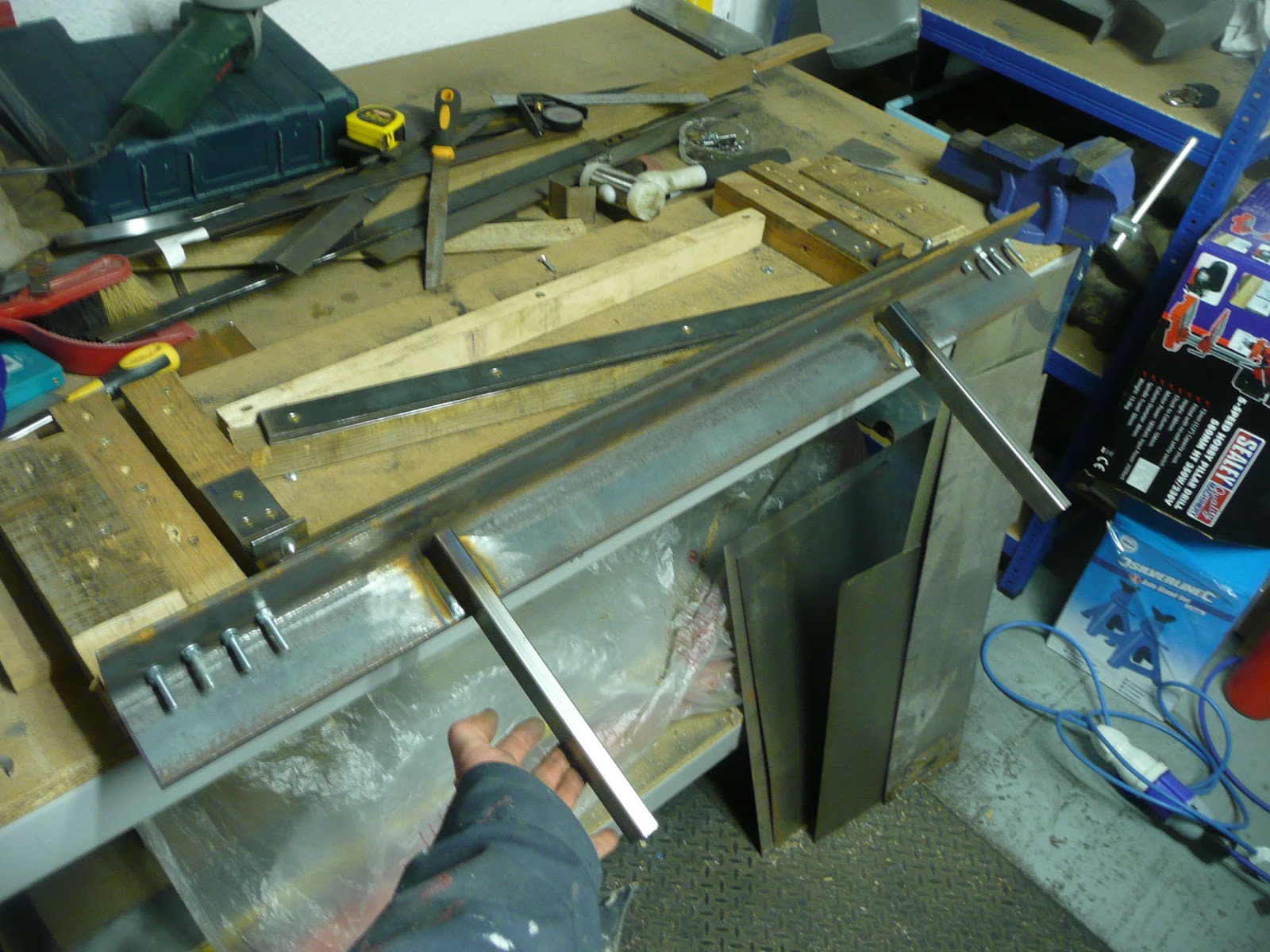
I basically had to make a Sheet Metal Brake or Bender to do the job. 'Off The Shelf' Metal Brakes, at least affordable ones (£50 odd), are only good for single bends and won't do Joggle Bends so the Brake I made out of scraps of MDF, Timber and Angle Iron can do them...hoorah! But the 'machine' needed plenty of fine-tuning to get it to work properly. Here's what it looks like...I can make the Joggle Bends by taking out the base plate you can see in the pic.. I won't go on about it!
But if anyone does actually ever read this and wants to know how I made it, post a comment! Anyone, Bueller, Bueller, Bueller...
I could only make about 30cm lengths of the plate at a time to any accuracy. I needed around 60cm total length so that's obviously two lengths which I'll weld together..duh.
Here are the results of the exercise - pretty much a perfect fit (to my great surprise!)
1. Where it needs to fit..
2. Lining the bits up..
3. Close up of the Joggle Bend..
So just as I'm about to start cutting and sanding the pieces so they fit perfectly together before I weld them, my disc sander blows a fuse...arghh. So that's been sent back to the factory for repair. When it's returned, I'll weld all this lot together and finish the job.
Phew!!
Anyway, when I cut the Trunk Floor out all those months back I had to trash a strip of metal that essentially stiffened the transmission/gearbox mounts. This innocent looking piece of metal mated perfectly to the trunk floor beneath it with Joggle Bends along either edge - a Joggle Bend is basically a step in the metal.
Here's the strip before I replaced the floor back in January this year..
I thought fabricating a new strip would be easy but I realise now that often the jobs that appear the simplest can infact be quite a P.I.T.A!
I basically had to make a Sheet Metal Brake or Bender to do the job. 'Off The Shelf' Metal Brakes, at least affordable ones (£50 odd), are only good for single bends and won't do Joggle Bends so the Brake I made out of scraps of MDF, Timber and Angle Iron can do them...hoorah! But the 'machine' needed plenty of fine-tuning to get it to work properly. Here's what it looks like...I can make the Joggle Bends by taking out the base plate you can see in the pic.. I won't go on about it!
But if anyone does actually ever read this and wants to know how I made it, post a comment! Anyone, Bueller, Bueller, Bueller...
I could only make about 30cm lengths of the plate at a time to any accuracy. I needed around 60cm total length so that's obviously two lengths which I'll weld together..duh.
Here are the results of the exercise - pretty much a perfect fit (to my great surprise!)
1. Where it needs to fit..
2. Lining the bits up..
3. Close up of the Joggle Bend..
So just as I'm about to start cutting and sanding the pieces so they fit perfectly together before I weld them, my disc sander blows a fuse...arghh. So that's been sent back to the factory for repair. When it's returned, I'll weld all this lot together and finish the job.
Phew!!
Saturday, 17 November 2012
Passenger Jack Post - 'Hacked Off!'
I could see the Long beneath the Jack Post had alot of rot which needs fixing...so off with the Jack Post with the spot weld drill bit, angle grinder and some brute force. The Long is the main structural member that runs along each side of the car at the base of the door opening - connecting the front and rear of the car effectively. It needs to be in great shape for a HP upgrade...
I should mention during this operation, Zoe came in with a cup of tea. I put the drill on my lap as I was sitting on the floor. Finished the cuppa then picked up the drill and inadvertantly pressed it on. It wound up my overalls and started to chew into my thigh!!! Funny looking back on it but it hurt quite alot at the time...daft bu**er! (and I don't mean butter!)
Jack Post succumbing....
Here's the view after the Jack Post has been removed...lots of holes! I'll replace the bad metal and put in a new Jack Post which I already have. This will be a tricky job for me but I think it could have been ALOT worse.
I'll take off the Sill Support which is the triangular bit with the two holes in on the right of the pic above and then weld in new metal to replace the rust.
It'll take a while to get this all done; so for now, I've just covered the area in cheapo primer to prevent surface rust starting..
I should mention during this operation, Zoe came in with a cup of tea. I put the drill on my lap as I was sitting on the floor. Finished the cuppa then picked up the drill and inadvertantly pressed it on. It wound up my overalls and started to chew into my thigh!!! Funny looking back on it but it hurt quite alot at the time...daft bu**er! (and I don't mean butter!)
Jack Post succumbing....
Here's the view after the Jack Post has been removed...lots of holes! I'll replace the bad metal and put in a new Jack Post which I already have. This will be a tricky job for me but I think it could have been ALOT worse.
I'll take off the Sill Support which is the triangular bit with the two holes in on the right of the pic above and then weld in new metal to replace the rust.
It'll take a while to get this all done; so for now, I've just covered the area in cheapo primer to prevent surface rust starting..
Passenger Rear Wing - What Lies Beneath!
Marked out the line to cut along in order to expose as much of the chassis beneath. Then....deep breath...gulp...cut along the line with a 1mm disc on a Dremel.
You can see the previous owner's repair job. Many of these plates/patches aren't properly welded - it definitely can't stay this way. I have the proper panel to weld in but it's a big ol' job for as novice like me! Check the pic below..
Looking upwards into that cavity shows more trouble..this bit will be fiddly because there's good and bad metal in close confines and the panel joins are tricky.. What's more I'll need to do some repair to the 'Longs' first - see the next post for more on that.
You can see the previous owner's repair job. Many of these plates/patches aren't properly welded - it definitely can't stay this way. I have the proper panel to weld in but it's a big ol' job for as novice like me! Check the pic below..
Looking upwards into that cavity shows more trouble..this bit will be fiddly because there's good and bad metal in close confines and the panel joins are tricky.. What's more I'll need to do some repair to the 'Longs' first - see the next post for more on that.
Friday, 2 November 2012
Passenger Rear Wing Paint Strip
...stripped the paint off the rear wing before I chop it off to get at the hell hole. Looks nice under all the crappy paint job.
Subscribe to:
Posts (Atom)